Technical Documentation TECHNICAL
Piezoelectric element characteristics
Piezoelectric element structure
A piezoelectric element is a solid actuator that produces displacement when voltage is applied. Forming electrodes on both sides of a piezoelectric ceramic plate and applying a voltage produces a distortion of about 0.1%.
Figure 1 shows the structure of a stacked piezoelectric element. A large number of piezoelectric ceramic sheets are stacked with internal electrodes formed on opposite sides, and insulators are placed every other layer on the sides to form external electrodes.
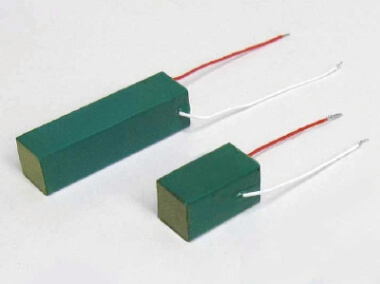
The side surfaces of the piezoelectric element are covered with resin for protection. There is also a metal case enclosed type that blocks outside air.
The features of multilayer piezoelectric elements include: (1) large generating force, (2) high resolution, (3) high-speed response, and (4) high electromechanical conversion efficiency.
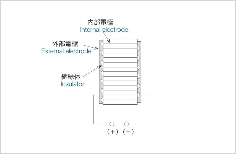
Fig. 1
Resin Exterior Dies
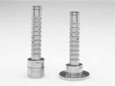
Metal Case Enclosed Type
Displacement of piezoelectric element
Hysteresis
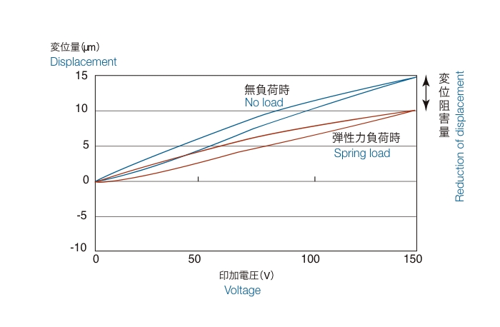
Figure 2 shows the amount of displacement when a voltage is applied to a stacked piezoelectric element. The piezoelectric element expands and contracts according to the voltage, but the displacement curves do not follow the same path when the voltage is increased (step-up) and when the voltage is decreased (step-down). This is called hysteresis (history), and it occurs at about 15 to 20% of the maximum displacement.
The displacement curve when the voltage application to the piezoelectric element is repeated several times shows a shift in the amount of displacement near a voltage of 0 V between the first and second repetitions, which is called a zero shift.
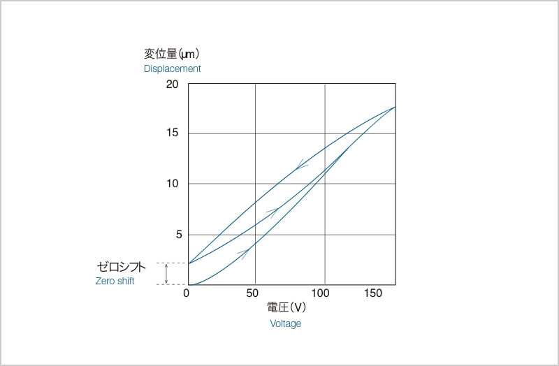
Fig. 2
Creep
Figure 3 shows the time variation of the amount of displacement when a constant voltage is applied to the piezoelectric element and held, and it can be seen that the amount of displacement changes gradually with time.
This phenomenon is called creep and is attributed to the polarization of piezoelectric ceramics.
The amount of creep increases with the width of the input voltage from the previous voltage value, and its direction is the same as the voltage rise or fall.
Because of these properties such as hysteresis and creep, the amount of displacement of a piezoelectric element cannot be uniquely determined by the applied voltage value alone.
When piezoelectric elements are used as a drive source for precision positioning devices, it is necessary to constantly control the applied voltage while measuring the actual amount of displacement (movement) using a displacement sensor in combination.

Fig. 3
Force generated by piezoelectric element
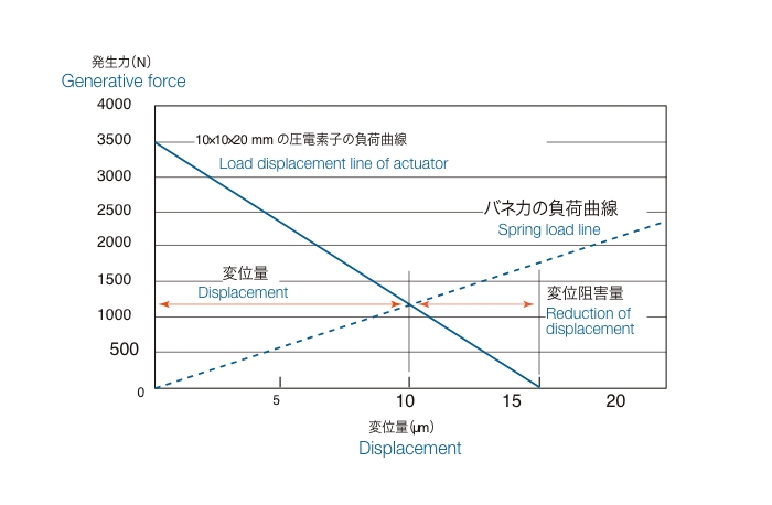
Figure 4 shows the forces generated by a stacked piezoelectric element. Since piezoelectric elements are elastic, they contract when pressure (load) is applied. The force that can be applied to it to return it to its original position by applying the rated voltage is called the maximum generated force.
The amount of displacement of a piezoelectric element differs when the applied pressure (load) is a constant load like a weight or when it changes gradually like a spring.


Fig. 4
When load (pressure) is constant
If the load (pressure) is constant, the rated displacement can be obtained with the rated voltage if the contracted position is used as a reference.
When load (pressure) varies
If the load (pressure) is an elastic force like a spring, displacement is only up to the point where the stiffness of the piezoelectric element is balanced by the stiffness of the spring, causing displacement inhibition.
Piezoelectric element of "metal case enclosed type"
The metal case enclosed type has a structure that shuts off the piezoelectric element from the outside air, making it less susceptible to the effects of atmospheric conditions.
Compared to piezoelectric elements with a resin exterior, they have superior durability against ambient temperature and humidity, and are less likely to deteriorate (life time) even when constant voltage is applied for a long period of time.
- Instruments and microscopes that handle liquids, such as biotechnology
- Environment with oil or mist on processing machine
- Usage in which the device remains stationary dwell (in standby) at a fixed position for a long period of time * The time in which the device is in operation is shorter.
- Usage in which the device remains stationary dwell (in standby) at a fixed position for a long period of time
* The time in which the device is in operation is shorter. - Use in locations where replacement (removal) is difficult in the event of failure
- Applications requiring high reliability
- High vacuum, ultra-high vacuum

Metal case enclosed type / Resin exterior type
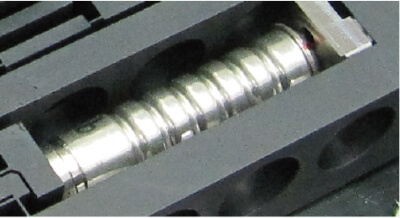
Integration into the main body of the stage
Insulation degradation of piezoelectric elements
One of the failure modes of multilayer piezoelectric elements is the short mode (breakdown) caused by insulation degradation. Although the mechanism that causes insulation degradation is not fully understood, it has been confirmed that the failure rate differs significantly between static usage (DC voltage applied) and dynamic usage (pulse voltage applied). In addition, it has been confirmed that, as with general electronic components, they are greatly affected by humidity in addition to applied voltage and environmental temperature. Moisture absorption of the element by the ambient environment during storage and operation can cause a decrease in *insulation resistance due to migration.
*Migration
A phenomenon in which Ag in the inner electrode is ionized and penetrated along grain boundaries by an applied electric field, leading to dielectric breakdown. This is likely to occur when a constant voltage is continuously applied in a high-humidity environment.
Contact Us about Technical Documentation
フォームが表示されるまでしばらくお待ち下さい。
恐れ入りますが、しばらくお待ちいただいてもフォームが表示されない場合は、こちらまでお問い合わせください。


